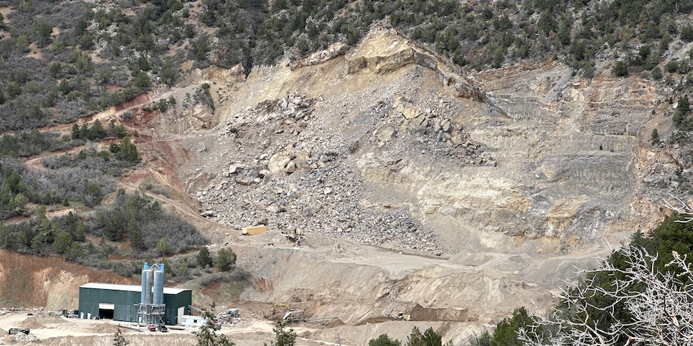
View of the Rocky Mountain Industrials limestone quarry. The rockslide occurred on the western / left side of the quarry. Photo by the Glenwood Springs Citizens’ Alliance, May 16, 2023.
Rock Failure Analysis and Stability report
Use this page to access the geotechnical report prepared by Kilduff Underground Engineering Inc. of Denver for Rocky Mountain Industrials (RMI). The report was submitted to the U.S. Bureau of Land Management on Aug. 30, 2023, as part of RMI’s Plan of Operations Modification proposal.
The Glenwood Springs Citizens’ Alliance obtained this report from the public website of the Colorado Division of Reclamation, Mining and Safety (DRMS).
DRMS and the U.S. Mine Safety and Health Administration (MSHA) are collaborating with BLM on permit enforcement actions following the massive rockslide that occurred at the RMI quarry on Jan. 18, 2023.
The Kilduff report:
- Describes the steeply pitched limestone layers present in the quarry area.
- Explains how the rockslide occurred on the quarry’s west side.
- Calculates the risk of another slope collapse happening sometime in the future on the quarry’s east side.
- Lays out recommendations for rockfall mitigation to protect workers during ongoing mining.
- Offers strategies for stabilizing the overhanging cliffs so RMI could expand the mine upward on the mountainside.
- Concludes with a recommendation to mine at least 500 vertical feet farther up the mountainside in order to remove the remainder of the limestone layers that collapsed in January.
Two Key Findings
1. More mining upslope
The quarry consists of three distinct layers of limestone. At the bottom is a thick, cohesive layer 175 to 200 feet thick. Atop this are two upper layers, each 10 to 15 feet thick. The layers are pitched at angles of 24 to 38 degrees, and are separated by thin, weak layers of shaley mudstone.
The January slide occurred when friction within the shaley mudstone gave way, breaking off the upper two layers and sending them tumbling down into the quarry below.
Site mapping of the slopes above the quarry show that the two upper layers of limestone pinch out and become less steep higher on the mountainside. Kilduff proposes mining upslope to the elevation where these upper layers disappear.
The report includes a contour map of the quarry, the rockslide area and the slopes above, prepared by Lewicki and Associates. That’s the Littleton firm that RMI used to develop its 2019 mine expansion proposal. The contour map proposes mining upward another 500 to 600 vertical feet.
The Kilduff report is explicit in arguing that more mining is essential to stabilize the limestone layers: “It is the opinion of [Kilduff] that the upper limestone layer should be removed completely from the highwall to minimize the risk of another release.”
2. Setback area for worker safety
The report analyzes the causes of the rockslide, assesses the risks of additional slope collapse, and lays out a recommendation for rockfall mitigation so mining could continue.
It calls for excavating rock from the toe of the debris pile to create a catchment basin, and constructing a 15-foot-high rockfall berm that would stop any new rockfall.
Kilduff’s report also defines a rockfall runout setback area that includes the locations for the catchment basin and rockfall berm, with this caution: “No man work shale be performed within the setback without additional stabilization or barriers.”
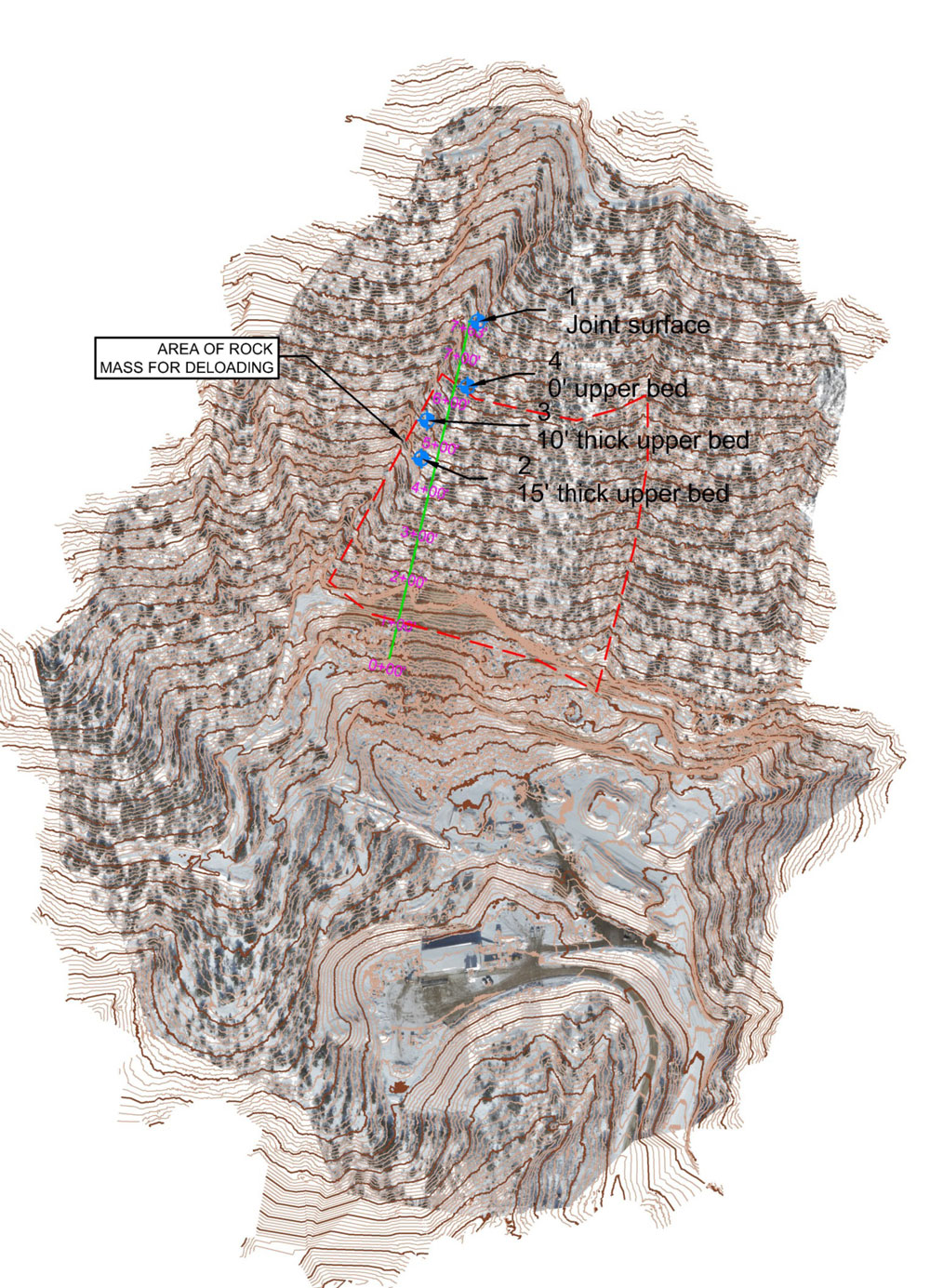
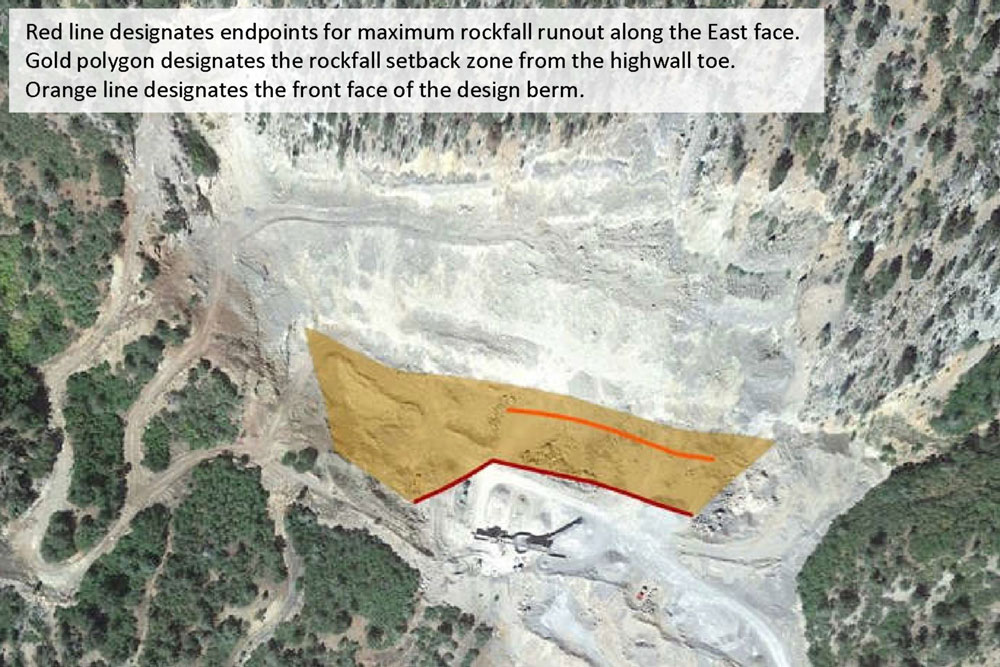
Figures: Rockfall, photo 2b, from the Kilduff report, Aug. 10, 2023.
Red line designates endpoints for maximum rockfall runout along the east face.
Gold polygon designates the rockfall setback zone from the highwall toe.
Orange line designates the front face of the design berm.
Important to note: the background aerial photo is of the RMI limestone quarry prior to the rockslide event
Links to the Kilduff Underground Engineering
“Rock Failure Analysis and Stability” report
Rock Failure Analysis and Stability
Main narrative, 23.7 MB, 18 pages
Appendix A Field Mapping Photographs
12.5 MB, 8 pages
Appendix B East Face Discontinuity Mapping
1.6 MB, 2 pages
Appendix C Kinematic Results
4 MB, 5 pages
Appendix D Planar Failure Results
2.9 MB, 5 pages
Appendix E Rockfall Modeling Results
12 MB, 24 pages
Appendix F July 2023 West Face Photos
7.4 MB, 5 pages
Appendix G Active Stabilization Design
8.1 MB, 16 pages
> Figures (cover page + 1 page of illustration)
Profile of Slide, 1.9 MB
Rockfall (with markings), 1.9 MB
Site Location, 1.7 MB
Direct access to the geotech docs on the Colorado Division of Reclamation, Mining & Safety Laserfiche search site.
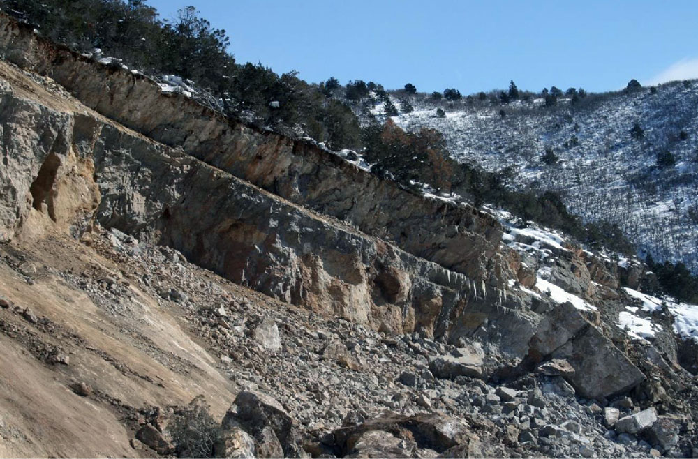
Appendix A, photo 3: Side view, looking east, of the two upper units of limestone with bedding acting as the slide plane. Photo by Kilduff Underground Engineering, Jan. 26, 2023.
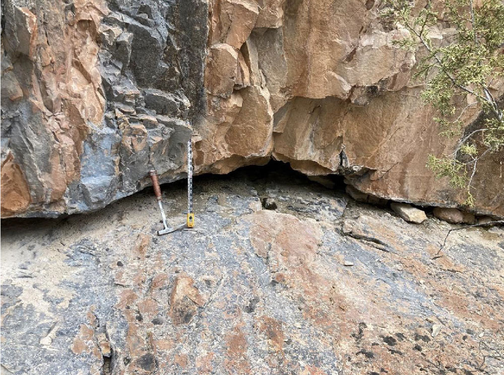
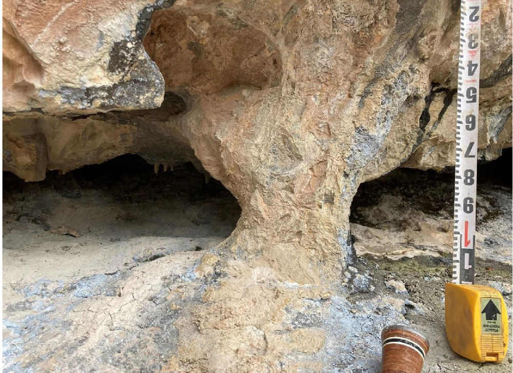
Appendix A, photo 10: Close-up of exposed interbed mudstone layer, eroded back from outcrop face approximately 3 feet. Photo by Kilduff Underground Engineering, April 14, 2023.